These pictures were current as of:09-25-2004.
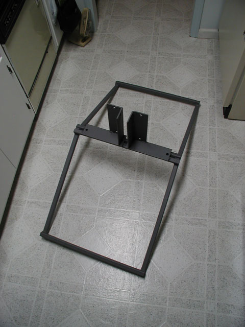
Fabricated roof peak mount using 1"x1" x.125" steel tubing and heavy 1/4" steel plates. The 2" OD mast will be bolted between the vertical up-rights so it can swivel up into position and then an additional bolt above to lock it into place vertically. The tubular steel is spaced to fit directly over rafter beams. Thanks to Rick Hill for building the mount for me! I ended up just setting this on the roof without using any hardware to secure it. I figure it's not going to move with all the weight and down force being exerted on it.
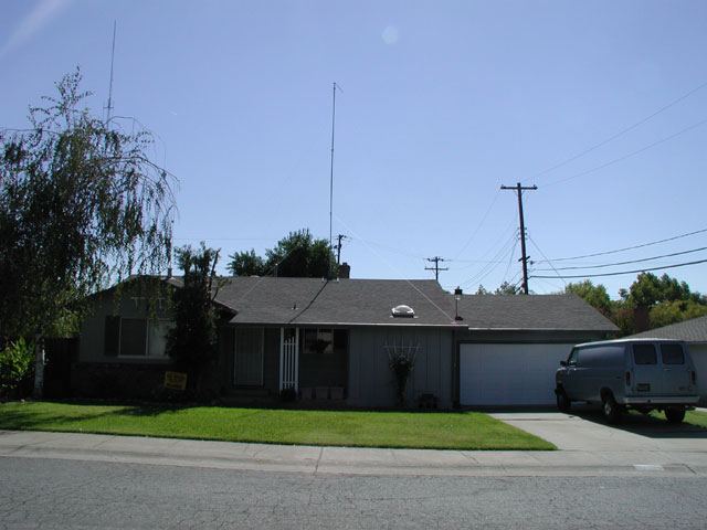
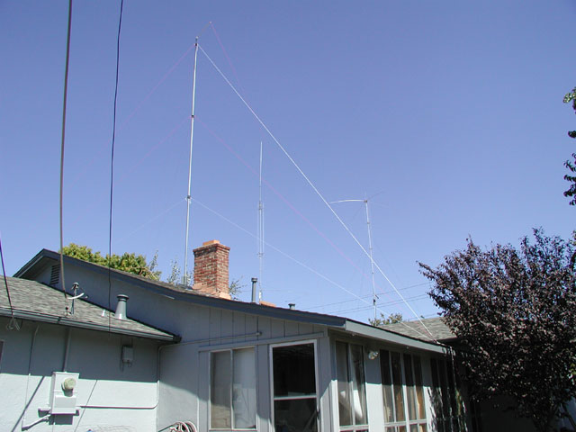
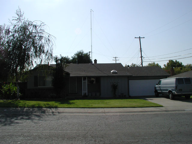
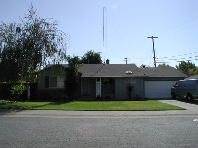
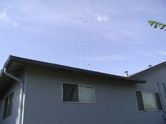
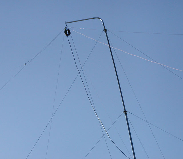
Front view showing mast temporarily at 30 feet. On top is a 3 foot length of pvc pipe with string attached so I could drag it around the yard to see what kind of length I can get down to various locations for a maypole consisting of 3 inverted "V's". The concern here are those 12.5KV high voltage lines at the right. It is 33 feet to the edge of the house from the base of the mast so the mast is clear of the lines if it were unlikely to fall in that direction. It would have been nice to put something on top of that mast but those power lines prevent that from ever happening.
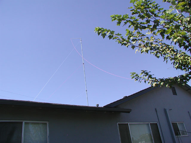
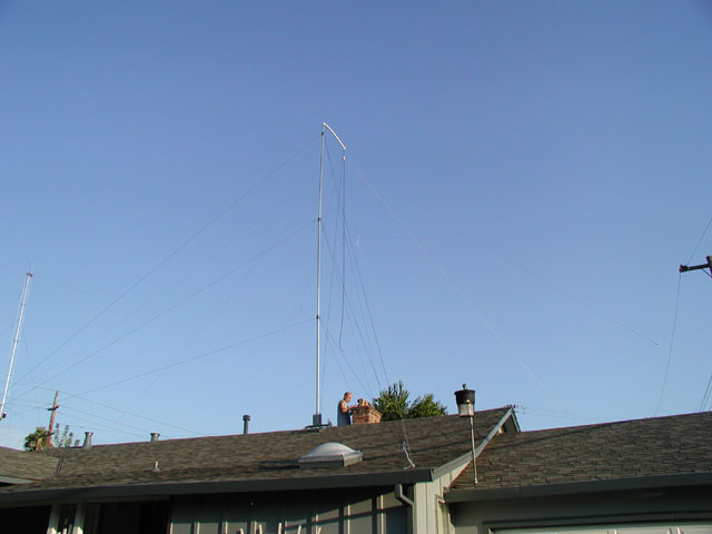
View from backyard looking up at the roof mast. By the way, at this point, the mast is temporarily being supported with mason string.
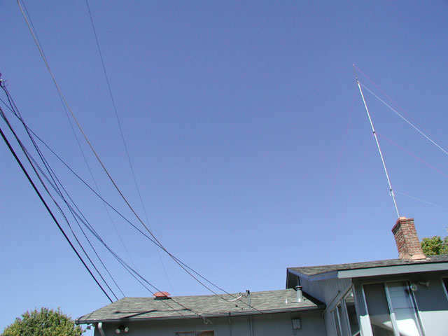
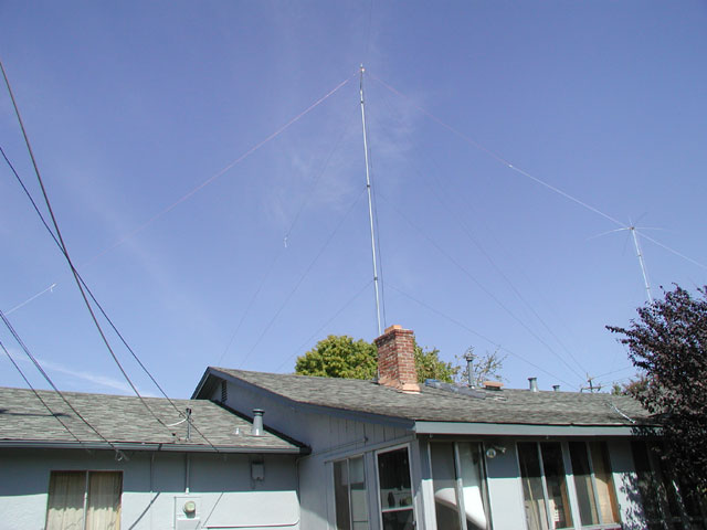
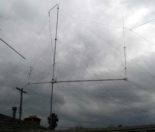
Another view from the backyard showing the roof mast in relation to the 12.5KV high voltage lines and all the other overhead utility lines.
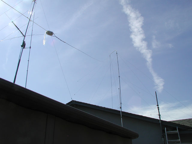
Same backyard view but taken from the South-West corner where the other end of the 75/80m dipole will be connected. The 40m dipole ends will attach to the East and West ends of the roof. The 20m dipole ends will attach to the front right guy point on the front side of the roof and the other end will be attached to the back corner of the roof. That location is behind the purple plum tree in this photo.
Originally, I was planning on mounting this on top of the Maypole mast. But after realizing the the mast needed to be at least 30 feet tall in order to fit the 75m dipole in the yard, these antennas would put the tip of the 2m Ringo at nearly 45 feet and would hit the high voltage lines if it were to fall in that direction. Shown are the Cushcraft ARX2B and ARX450B antennas mounted on a 6 foot cross-arm . I fabricated the mounting plates using 3/16" aluminum plate stock and "U"-bolts. You can see the pulley hanging below the 70cm Ringo which would have been used to hang the maypole. I later lengthened the cross-arm and mounted it at the 10 foot level on the mast.
Now for pictures of the Maypole antenna itself. Pictures current as of 10/05/2004.
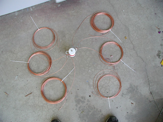
This Maypole consists of 3 inverted "V's" for 75m, 40m and 20m all soldered to a center insulator
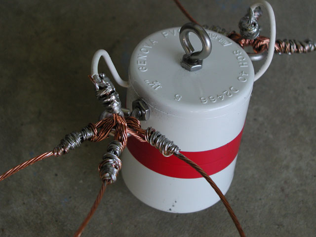
Center insulator (from The Radio Works) construction.
Initial test installation using 1" PVC stand-off.
Side view of the antenna. Notice the bend in the PVC pipe. It's not strong enough! Also note I removed the temporary mason string guy lines and used 1/8: kevlar coated Dacron.
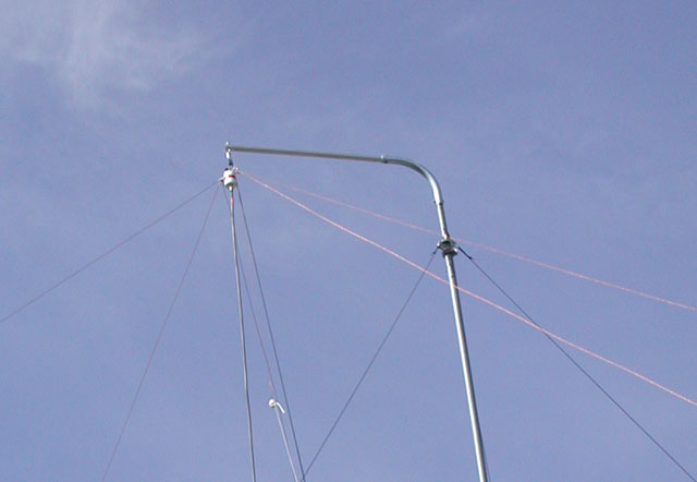
Here it is after replacing the PVC stand-off with 1" EMT 90 degree conduit bend and 3 feet of 1 1/4" aluminum tubing. I was surprised to find out just how much down force there was with this antenna. After all, there are 6 wires plus coax pulling down on it.
View from backyard Southwest corner where one end of the 75m dipole attaches.
View from backyard Southeast corner where one end of the 20m dipole attaches.
View from backyard Northwest corner where other end of the 75m dipole attaches.
Close-up of the new stronger stand-off solution.
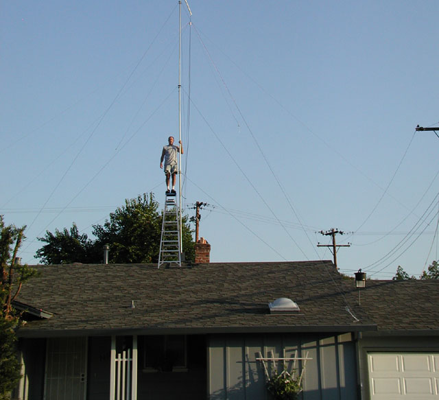
Fortunately, I like heights.
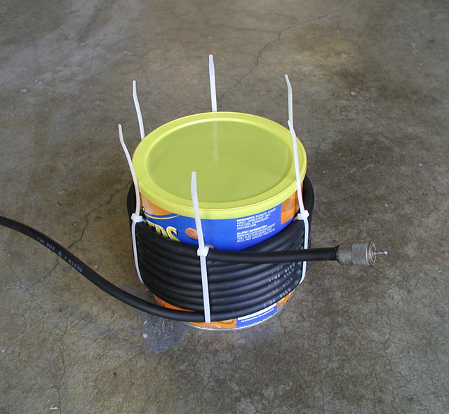
Initially I had some RF getting onto my audio so I suspected possible RF coming down the coax shield. So I built this coax choke coil. Eight turns on a roasted peanut can that is a hair over 6 inches in diameter. Found out that I had a bad shield on my Kenwood microphone connecter and that solved the problem. This choke probably helped but I noticed it reduced the usable bandwidth of the antenna. I later replaced this with a Unidilla W2DU inline current baln which didn't seem to effect the bandwidth as did the coil.
Coax choke hanging from center insulator. Tied to top of insulator for support.
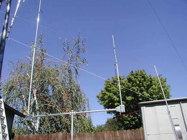
And here are the 2m and 70cm Ringo Rangers on a longer cross-arm and mounted to the Maypole mast at the 10 foot level. It's starting to look a bit busy and messy but what's really important here anyway?